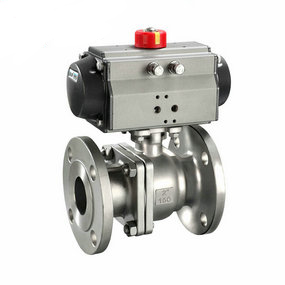
Inaccurate display of intelligent anti-corrosion pneumatic regulating butterfly valve 5. Design and manufacture of pneumatic ball valve The application of CAD, CAM and FMS in the valve industry has brought the design and manufacture of pneumatic ball valve to a new level. Not only has the design and calculation method of valves been comprehensively innovated, but also the heavy and repetitive routine design work of professional technicians has been alleviated, so that technicians have more energy to improve and improve product performance and new product development, shorten the research and development cycle of new products, and comprehensively improve labor productivity, Due to the application of CAD/CAM, the valve stem spiral flat, which is produced by computer aided design and computer aided numerical control machine tools, has emerged, making the metal sealed pneumatic ball valve free of any scratch and wear during the opening and closing process, thus greatly improving the sealing performance and service life of the pneumatic ball valve. When the pneumatic ball valve is fully opened, the flow resistance is very small, almost equal to zero. Therefore, the equal diameter pneumatic ball valve is widely used in oil and gas pipelines because it is easy to clean pipelines. Since the ball of the pneumatic ball valve is wiping in the opening and closing process, most pneumatic ball valves can be used in the medium with suspended solid particles, and the materials based on the sealing ring can also be used in the powder and granular medium.
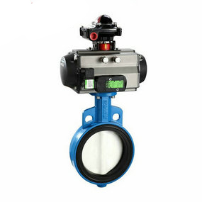
2. The pipeline has micro flow inspection flow chart item 2. Subjectively, it is believed that there is no flow in the flow sensor, but there is actually a trace flow. This kind of fault is mainly caused by the poor tightness of the stop valve of the original flash foot pipeline, and the small leakage detected by the electromagnetic flowmeter is misunderstood as zero point change or instability. The valve is often used for a long time or the valve is not fully sealed due to liquid dirt, especially for large valves. Another common reason is that there are several branch pipes in addition to the upper pipes of the flow instrument, and the valves of these branch pipes are forgotten or ignored to close. Sometimes, it is difficult to confirm that there is no flow in the pipeline system on site. At this time, as shown in Figure 4, a small caliber leakage monitoring valve 3 can be set between the stop valves 1 and 4 in front and behind the flow sensor 2 to observe whether there is enough leakage.