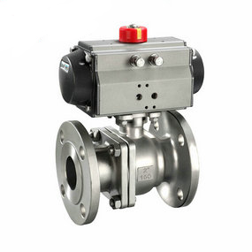
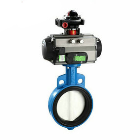
Is normal pneumatic hard seal soft seal ball valve related to working pressure? Rubber pneumatic butterfly valve air conditioning unit damper water pump damper
According to whether the shock absorber can rotate or not, the shock absorption can be divided into fixed shock absorption and rotary shock absorption. Fixed vibration damping refers to taking vibration damping measures for fixed parts, such as base shock absorber; Rotating vibration damping refers to taking vibration damping measures on rotating bodies, such as rotor vibration damper, bearing vibration damper, etc. Fixed vibration reduction mainly refers to base vibration reduction, which is widely used. Rubber shock absorbers, spring shock absorbers, fluid shock absorbers, etc. can be used for base vibration reduction. Different shock absorbers are used according to different conditions. Rubber shock absorbers are commonly used.
Rubber is an ideal damping material and has damping effect on vibration. Rubber has great linear flexibility, can be stretched to break without losing its elasticity, and can accept alternating stress without fatigue. Rubber, like water, can hardly be compressed. It only produces elastic deformation after being pressed, but its volume remains unchanged. When the temperature is below - 30 ℃, the elasticity of rubber will be significantly reduced, so the rubber shock absorber should not work in severe cold conditions; At the same time, rubber is not resistant to high temperature, and its working temperature should not exceed 75-80 degrees. The compressive strength of rubber is much greater than the tensile strength.
The stretching length of rubber is generally about 6 times larger than the tightening interval. When rubber is stretched or compressed, its natural vibration frequency is not the same.
Pay attention to the design of directly buried pipeline compensator
Universal compensator (contraction joint, expansion joint) is mainly used to compensate the axial displacement of pipeline and a small amount of lateral displacement of pipeline, shock absorption and noise absorption. It has the advantages of simple pipeline design, easy installation, low cost, etc. However, when it is used for large diameter pipeline system, due to the excessive internal pressure thrust, special attention should be paid to the strength of the fixed support to avoid the collapse of the fixed support. Universal compensation can be used as axial compensation or transverse compensation alone, but it is not suitable for angular compensation alone.
Precautions for devices
1. The chloride ion content of the medium is ≤ 25PPM.
2. It is strictly prohibited to splash welding slag on bellows.
3. It must be marked according to the product flow direction.
4. Both ends of the bellows must be reasonably set with guide support and fixed support. (See "Setting of Corrugated Compensator Pipe System Support" for details) 5. It is not allowed to use the deformation of the corrugated compensator to forcibly adjust the device error of the pipe system position.
6. Stop lifting with device pull rod or limit pull rod.
7. After the end of the device, remove the transportation rod and the limit rod with yellow mark.
Sometimes, in order to reduce the number of fixed supports, the piping system of the directly buried steam pipeline is often arranged in the "stagnation point" mode: there is no fixed point at the midpoint of the pipeline between two adjacent compensators with the same specification and model of the directly buried pipeline. When the pipeline shrinks averagely under heat, a relative equilibrium point of force, namely, stagnation point, must be formed between the two compensators. Theoretically, taking this point as the boundary, the pipeline shrinks evenly in the left and right directions. It is generally believed that the equilibrium point of the force may be slightly offset due to the uneven force on the pipeline. Generally, 20% margin is used to stop thinking about the setting of the compensator. It is thought that this arrangement is worth discussing. Our company has a business unit built in 1992 φ 630 steam directly buried pipeline and this layout method are adopted. The spacing between fixed supports is 80 meters. Two compensators are provided with the same specifications and models, both of which are 120 mm. In 2000, the replacement of this section of pipeline was stopped. After disassembly, it was found that one of the compensators had been flattened, with a contraction amount of 200 mm. The other one not only did not play the role of compensation and contraction, but was lengthened by 50 mm, The extension of one compensator causes excessive contraction of the other compensator, which causes both compensators to be damaged and fail. The reasons for this situation are complicated: First, the compensator itself has a large mass deviation, and although the model and specification are the same, the stiffness value gap is large and cannot be contracted freely; Second, due to the influence of pipe processing and manufacturing quality and device quality, the pipes on both sides of the "stagnation point" fixed support are not evenly stressed, resulting in large stagnation point offset, and the "stagnation point" is not fixed, which makes the corrugated compensator unacceptable and eventually leads to damage. Unless the compensator itself is greatly improved to ensure that the uniformly distributed limit of the compensator makes the stiffness balance of the compensator tend to diverge, otherwise, under the condition of using ordinary compensator, only one compensator guide line shall be set between every two fixed supports according to American EJMA rules.