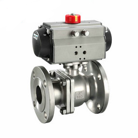
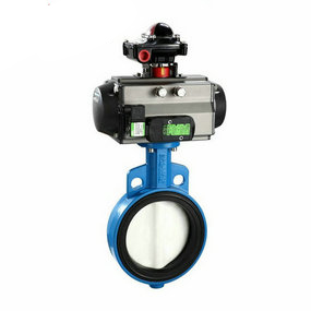
LD pneumatic louver round butterfly valve short circuit Working principle diagram of double acting pneumatic pneumatic ball valve (1. Pneumatic head 2. Solenoid valve 3. Filter pressure reducing valve 4. Air source) Figure 1 is the working principle diagram of a set of double acting pneumatic pneumatic ball valve. Compressed air (air source) first passes through the filter pressure reducing valve to remove the moisture, oil and solid dust particles contained therein, and adjust the system pressure to the set value to provide stable air source pressure. Then, the gas flows into the solenoid valve inlet a, flows into the pneumatic head from the air port b, and pushes the piston to act. The exhaust channel is d~E. After the coil is powered on, the solenoid valve reverses. The gas flows into the pneumatic head from the air port d, and pushes the piston to act in the opposite direction. The exhaust channel is b~c. Figure 2 Schematic diagram of single acting pneumatic pneumatic ball valve (1. Pneumatic head 2. Solenoid valve 3. Filter pressure reducing valve 4. Air source), At the same time, the spring in the pneumatic head is compressed. In case of failure (loss of air or power), the solenoid valve returns to the spring position, the air source is blocked, the pneumatic head spring releases the compression force, and pushes the piston to move in the opposite direction. The exhaust channel is b~c. The valve can be left at the set open or closed position to prevent accidents.
Device and composition of thrust free rotary compensator
In the design of the heat supply network, the designer should change the elevation and direction from time to time according to the requirements of the astronomical environment and urban planning, so that the heat supply network can be divided into many sections with different elevations, different directions and short linear intervals. If the thermal compensator of these straight pipe sections relies on the existing sleeve, the wave or gate type compensator cannot achieve the desired effect, Therefore, based on the proposal of many experts, our company developed the Shengli GSJ-V series rotary compensator and stopped its trial use on the Liyang heat supply network in September 1998, achieving success. The outline of GSJ-V series is shown in the figure below:
1. Characteristics of GSJ-V series rotary compensator Compared with commonly used compensators such as sleeve, wave type and gate type, this compensator has the following characteristics:
① The compensator does not generate internal pressure thrust (or blind plate force), so the fixed supports at both ends of the compensator can be made very small.
② In order to avoid damage to the sleeve and wave compensator, the design and device request "severe alignment", so an additional guide bracket must be added in front of each compensator. This compensator does not have the problem of "alignment", so no additional guide support is needed. ③ The compensator does not need to reserve heat expansion and contraction during heat preservation, so the heat loss is small. ④ The compensator uses the most advanced sealing information in China at present, and has a more reasonable sealing surface structure, so that the wear of the sealing information and sealing surface is extremely slight, which can ensure that no leakage will occur in a longer period of time. ⑤ The rotary cylinder of the compensator is equipped with a stop ring and antifriction and centering bullets, It greatly increases the reliability of work. ⑥ The rotary compensator has two basic combinations, dozens of changes, and the compensation can reach 1800mm. One of the compensators can replace several sleeves or wave type compensators. 2. Principle and selection points of GSJ-V series rotary compensators. A Operating principle and layout of rotary compensators: compensation principle of GSJ-V series rotary compensators, It is a pair of forces with equal size and opposite direction formed by a couple of double rotating cylinders and L arm. The arm coil rotates around the center of the Z axis to reach the absorption of the thermal shrinkage generated by the heat pipes on both sides of the arm. ① Π - type combined rotary compensator (Fig. 2 and 3) When the compensator is placed between two fixed supports, When the heat pipe is running, both ends have the same amount of heat shrinkage, the same amount of heat expansion and the same thrust of heat expansion, rotating the couple around the center 0 θ Angle to reach the thermal expansion △ with opposite directions and same size at both ends of absorption. When the compensator is not arranged in the center of the two fixed supports, but tends to the shorter end of the heat pipe, the center 0 of the coupling arm L tends to wind around the shorter end during operation to absorb the contraction amount △ 1 and △ 2 with opposite directions and different sizes at both ends.
The arrangement of this kind of compensator is similar to that of the spherical compensator. When absorbing the thermal shrinkage, the coupling arm rotates to 1/2 θ The maximum swing y value of the hot pipe occurs at the time of expansion, so the spacing from the first guide support of the compensator should be increased. (See Table 3) It is true that the absorption of thermal expansion increases with the angle θ Or the coupling arm L increases, but in order to limit the excessive swing of y θ The value should not exceed the recommended value in Table 4, and L should be within 15-3 meters. The compensator has wide compliance, and can be arranged for parallel way corner way and underground transition to overhead. ② Ω type combined rotary compensator (Fig. 4 and Fig. 5) Ω type combined rotary compensator is mainly used in the straight pipe section of the hot pipe. It is symmetrically arranged on both sides of the heat pipe, and consists of two pairs of couple arms L and a pair of rotating cylinders in the shape of Ω. Relying on the heat pipe between the two fixed supports, the two pairs of couples are driven to rotate synchronously with the thermal expansion force pointing to the compensator, as shown in Figure 4 θ The angle and B spacing change from large to small, so as to reach the maximum absorption of thermal expansion △ max=Bmax BminB, selection points ① п H=rotating cylinder length+2 × 1.5DN, W=2 × (rotating cylinder length+2 × 1.5DN). ② The GSJ-V rotary compensator is a new type of compensation installation, and its compensation ability is particularly large. Therefore, when using this compensator to stop long interval compensation, the guide strut ③ can be set according to Table 2 because п There is lateral swing when the Type A combined compensator stops, so it is not allowed to set a guide bracket within a certain interval on both sides. See Table III ④ θ The size of has a direct impact on the service life of sealing materials. The larger the pipe diameter is, θ The smaller it should be, the company has regulated its maximum value and hopes to calculate it θ The value does not exceed the maximum value. ⑤ п The compensation amount △ of the combined compensator is fixed. When п When the type combined compensator is installed between two fixed supports, the compensation amount △ at either end is: △=0.7071L The total compensation amount between two fixed supports is 2 △. Between two fixing brackets п When the type combined compensator is installed on a fixed support and the short arm heat pipe is 1/2 of the long arm (the long arm heat pipe request △ 2=L2/L1 △ 1), the thermal expansion of the long arm heat pipe △ 1=0.7071L1 √ 1-cos θ, The thermal expansion of the short arm heat pipe △ 2=0.5 △ 1 compensator is also known as a contraction joint, or expansion joint. The utility model is composed of a bellows (an elastic element) which constitutes the main body of the utility model, an end pipe, a bracket, a flange, a conduit and other accessories. It belongs to a compensation element. The effective expansion deformation of the bellows of its working body shall be applied to absorb the dimensional changes of pipelines, conduits, containers, etc. caused by thermal expansion and cold contraction, or to compensate the axial, transverse and angular displacement of pipelines, conduits, containers, etc. It can also be used for noise reduction and vibration reduction. It is widely used in modern industry. For heat supply, in order to avoid deformation or damage of the pipeline due to thermal elongation or temperature stress when the heat supply pipeline heats up, it is required to set a compensator on the pipeline to compensate for the thermal elongation of the pipeline, thus reducing the stress on the pipe wall and the force acting on the valve or support structure.