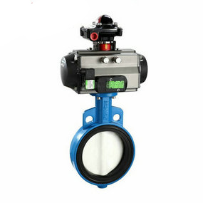
Two wire pneumatic American standard butterfly valve has no reading Alternative automobile shock absorber extended from spring shock absorber
Many people say that spring shock absorber is a kind of automobile shock absorber. This kind of talk is true and wrong, mainly because the latter belongs to the former, but the former does not belong to the latter. Therefore, this sentence can be changed into that the automobile shock absorber is a spring shock absorber, and it is an alternative, because its shape is different from the ordinary one.
The spring damper is a mechanical element used to restrain the vibration and impact from the outside when the spring rebounds after vibration absorption.
Spring shock absorber can be divided into:
1. Double acting spring shock absorber is a shock absorber that can reduce vibration in both the tightening stroke and the recovery stroke;
2. One way acting spring damper is a damper that only works during the recovery stroke.
The structure of spring damper generally includes:
Piston rod - working cylinder - piston - stretching valve - oil reservoir - tightening valve - compensation valve - flow valve - guide seat - dust cover - oil seal - spring.
The elbow force balanced bellows compensator is used for the connection between equipment and equipment. Its function is to compensate the heat shrinkage of the pipeline between two equipment, reduce the force of device error on the equipment and facilitate the device. The bending force balanced corrugated contraction is adopted to save energy, so that the equipment is not subject to the blind plate force generated by internal pressure. The rotary compensator improves the stress of the equipment, and the equipment is fixed at random.
The corrugated contraction joint has excellent flexibility and excellent performance when it is used to absorb the displacement generated by pipe heat contraction and the vibration generated by the machine. However, due to its excellent flexibility, if the device is improper, it will not only fail to play its excellent performance, but also easily be destroyed. Therefore, it is very important to correctly stop the support design and force calculation for the pipeline with contraction joints, calculate the transverse and longitudinal displacement and its force state, and accurately select the spacing between various supports and supports.
(1) The bellows contraction joint shall be selected according to the demand of the pipe system and the rated compensation amount. The pretension and compression test of the bellows contraction joint shall be stopped before leaving the factory. The pretension and compression test must meet the design requirements.
(2) The bellows contraction joint selected shall meet the application requirements, and its specification and model shall meet the design requirements and be different from the pipe system design. Contraction joints that do not meet the design requirements shall not be used.
(3) The corrugated pipe contraction joint with diversion pipe shall insist on diverging from the flow direction of the medium, so as to prevent the collection of sundries from affecting the use of the corrugated pipe contraction joint.
(4) It is forbidden to use the deformation of the bellows contraction joint to forcibly adjust the device error with the pipeline when installing the bellows contraction joint, so as not to affect the normal operation function of the bellows contraction joint. The rotary compensator will certainly reduce the service life of the bellows contraction joint.
(5) The bellows shrink joint device shall be installed in cold state, and the device error shall be controlled at: the center line of the interface between the two ends of the pipe and the bellows shrink joint shall be kept on the same center line, the coaxiality error shall be ± 5mm, and it shall not exceed ± 15mm under working state; The deviation displacement angle from top to bottom or from left to right is ± 0.1 °; The reasonable device length of contraction joint is L ± 5mm.
(6) After the installation of bellows contraction joint, remove the auxiliary positioning components and fasteners used as devices and transportation on the bellows contraction joint as soon as possible, and adjust the limit installation to the regular position according to the design requirements, which is the ability for the pipeline to have sufficient compensation under environmental conditions.
(7) For bellows contraction joints and pipes used for gas medium, temporary supports shall be added before filling water to support the weight of liquid medium when hydraulic test is conducted with liquid (water).
(8) During the initial commissioning, maintenance measures shall be taken for the bellows contraction joint at the parts with large air flow impact. After the pipe system operates normally, maintenance and installation shall be removed. The direction of the medium shall be different from the arrow direction of the bellows contraction joint.