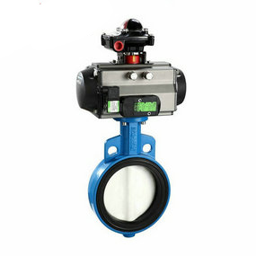
Specification and Model Table of Flanged Pneumatic Butterfly Valve Is Port 2 Open or Closed? Many factors need to be considered when designing pneumatic ball valves.
First of all, the weight and volume of the shock absorber must be considered when designing the shock absorber, and the shock absorber must have certain damping characteristics.
Secondly, the design of pneumatic ball valve should also consider the future service environment, and the pneumatic ball valve designed to withstand the ambient temperature is affected by other factors.
Third, since the pneumatic ball valve equipment has a certain bearing capacity, its load needs to be considered in the design to avoid excessive load in the future use process, resulting in greater problems.
Fourthly, the design of shock absorber must consider its damping performance to ensure that it can better meet the needs of application.
The sine load of ball valve damage can be constant amplitude load or variable load with known change rule. Regardless of the type, as long as the known fatigue strength value of the ball valve and the measured or calculated stress level of the components are used, one of the methods in the cumulative loss theory described above can be used to estimate the fatigue loss of the cumulative pneumatic ball valve. For constant amplitude load levels, the Miner criterion is an effective standard. The material strength can be determined by the test of constant amplitude load level.
For the sinusoidal load whose amplitude variation law of pneumatic ball valve is known, the Henry nonlinear loss theory is more accurate. The same result will appear when the scanning frequency passes through the resonance frequency of the ball valve of the test piece under the environment of the sinusoidal scanning test. It can be seen from Henry's nonlinear theory that the cycle ratio on the load level of each pneumatic ball valve must be calculated.
Under the sinusoidal scanning test of ball valve pneumatic ball valve, the calculation method of the cycle ratio of various load levels is as follows: from the pneumatic ball valve or strain gage of ball valve fixed on the pipeline and the known test frequency scanning range, the characteristics of the response changing with frequency can be known, so that the response stress level can be divided into various amplitude levels. The duration of amplitude level of each pneumatic ball valve is known, so when the average frequency of each level is known, the cycle ratio of each level can be calculated, and then the cumulative loss can be estimated.
The above is the main content of this article. For more information, please call 021-60344211


