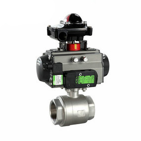
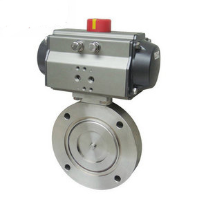
What is the diameter of the pneumatic segmented butterfly valve? Working principle diagram of double acting pneumatic pneumatic ball valve (1. Pneumatic head 2. Solenoid valve 3. Filter pressure reducing valve 4. Air source) Figure 1 is the working principle diagram of a set of double acting pneumatic pneumatic ball valve. Compressed air (air source) first passes through the filter pressure reducing valve to remove the moisture, oil and solid dust particles contained therein, and adjust the system pressure to the set value to provide stable air source pressure. Then, the gas flows into the solenoid valve inlet a, flows into the pneumatic head from the air port b, and pushes the piston to act. The exhaust channel is d~E. After the coil is powered on, the solenoid valve reverses. The gas flows into the pneumatic head from the air port d, and pushes the piston to act in the opposite direction. The exhaust channel is b~c. Figure 2 Schematic diagram of single acting pneumatic pneumatic ball valve (1. Pneumatic head 2. Solenoid valve 3. Filter pressure reducing valve 4. Air source), At the same time, the spring in the pneumatic head is compressed. In case of failure (loss of air or power), the solenoid valve returns to the spring position, the air source is blocked, the pneumatic head spring releases the compression force, and pushes the piston to move in the opposite direction. The exhaust channel is b~c. The valve can be left at the set open or closed position to prevent accidents.
1、 Before use, the pipeline and the overflow part of the valve body shall be cleaned with water to prevent residual iron chips and other sundries from entering the inner cavity of the valve body.