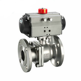
Composition and structure of hydraulic pneumatic flange type three eccentric ball valve The movable cutter head designed for mass machining of pneumatic ball valve shell not only ensures machining accuracy (concentricity), but also facilitates assembly and disassembly (assembly and disassembly time only takes more than 20 seconds). By compensating the error of the arc radius of the tool tip, the accuracy of adding soil on the radius of the arc surface is effectively guaranteed. This machining method is suitable for machining the inner surface of most pneumatic ball valve shells with disassembly holes.
What should we pay attention to when installing the ripple compensator? The connection mode of corrugated compensator is divided into flange connection and welding. The directly buried pipeline compensator is generally welded (except for trench devices). Precautions for corrugated compensator device: 1. Before installing the product, check whether the model and specification of the compensator must meet the design requirements of the whole pipe system. 2. Only one compensator or a group of angular type compensators can be installed between two fixed supports. 3. The fixed support must have sufficient strength to ensure that the compensator will not be damaged; The guide support must have sufficient guidance, or it will affect the transmission of pipeline displacement. 4. Compared with rigid pipes, corrugated compensators are much easier to install. Some deviations of pipes can be compensated by compensators, but this does not mean that there is no requirement for pipe devices. If the device has absorbed large displacement during operation, its service life will be affected. Therefore, it is not recommended to use a compensator on the guide line to compensate the device deviation. 5. Generally, the type of compensator listed in the sample does not absorb torque, so the compensator is not allowed to suffer torque during installation. 6. For the compensator with a draft tube, pay attention to make the direction of the draft tube diverge from the moving direction of the medium (according to the flow direction marker of the compensator). The hinge rotation plane of the plane angular compensator should be different from the displacement plane
7. For contraction joints that need to stop "cold tightening", the auxiliary components used for pre deformation shall be removed after pre deformation of the compensator.
8. After the completion of the piping device, the auxiliary positioning mechanism and fasteners used for device transportation and maintenance on the compensator shall be removed immediately, and the limit installation shall be adjusted to the regular position according to the design requirements, so that the piping system can be fully compensated under the environmental conditions.
9. In addition to the pre deformation of pre tension and compression or "cold tightening" required by the design, it is strictly prohibited to use the method of bellows deformation to adjust the device deflection of the pipeline, so as not to affect the normal function of the compensator, or it will reduce its service life and increase the load of the pipeline system, equipment and support components.
10. The neutral alignment of the pipeline is better. If there is no other way to ensure it, the method of cutting off equal length pipes after laying straight pipes and then installing contraction joints can be used to ensure it.
11. The insulation layer shall be placed on the maintenance sleeve outside the compensator, not directly on the bellows. Insulation materials containing chlorine shall not be used.
12. During the installation, welding slag shall not splash on the surface of the bellows or cause other mechanical damage to the bellows.
13. The support must meet the design requirements. It is strictly prohibited to test the pressure in the pipeline before the support is installed, so as to avoid damaging the compensator.
14. Compensator allows system pressure test not exceeding 1.5 times of nominal pressure.
15. For the compensator used for gas medium and its connecting pipeline, when conducting the hydraulic test, it is necessary to consider whether it is necessary to add a temporary support to the receiving of the compensator to bear the load when filling water.
16. The water for hydraulic test must be clean and non corrosive, and the content of chloride ion in the water shall not exceed 25ppm.
17. After the hydraulic test is completed, the accumulated water in the bellows shall be drained as soon as possible, and the inner and outer surfaces of the corrugated shell shall be blown dry quickly.
18. During the operation of the pipeline with compensator, the opening and closing of the valve shall be stopped step by step to avoid the sudden change of temperature and pressure in the pipeline and the formation of support or contraction joint damage.