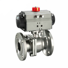
How many openings does the battery powered pneumatic solenoid butterfly valve have? Generally, when the control personnel are in the station or control room, they are required to have reliable control performance on the valve, and the valve itself is required to have protective and explosion-proof measures. Especially for long open valves, it is required to cut off accurately in case of sudden change. Therefore, reliable control performance has become the focus. In view of the above conditions, Q41WC series of sulfur resistant pipeline valve hard sealed pneumatic ball valve has been launched. The ball and integral seat are coated with chromium carbide and tungsten carbide using rocket application technology. This will increase the surface hardness by nearly an order of magnitude, which is superior to the conventional welding overlap reinforcement technology. The high-strength inconel x-750 spring forces the valve ball into the valve seat. This design solves many of the problems that occur in the setting up of trunnion bearings and corrosion. The free clearance between the valve ball and the valve seat is eliminated. Unlike the floating pneumatic ball valve, the design does not require upstream pressure to provide a tight seal. The spring makes the valve self compensating and provides anti-static protection.
Layout and position setting of rotary compensator in pipe network
The working principle of the spherical compensator is relatively simple. In addition to being able to rotate the arbitrary angle along the axis, it can also make a certain angle bending. This product uses this angle bending, and two or three of them are matched into a group to absorb the thermal shrinkage of the pipeline, so as to achieve the purpose of thermal compensation.
The rotary compensator has a variety of arrangements, which are relatively sensitive to use, but usually two arrangements are mainly used in the design: one is to arrange two compensators on horizontal or vertical Z-shaped pipes; The second is to arrange three compensators on the level L-shaped pipe.
1. Two spherical compensators are arranged on the Z-shaped pipeline. If the laying route of the heating pipeline is a straight line with flat terrain and no obstacles, the product should be centrally arranged on the Z-shaped curved pipeline similar to the square compensator. It has three ways. The trench laying degree is centralized on the side; The overhead low support shall be laid upward in a centralized manner; The overhead high support shall be laid downward in a centralized manner.
2. Three L-shaped pipes are arranged on the degree. When the laying of heat supply pipeline needs to turn, three L-shaped pipes can be arranged on the degree, one on the long pipe section and two on the short pipe section, to absorb the heat contraction of the heat supply pipe section. This arrangement can be laid in the trench or overhead.
According to the usual practice, the axial type corrugated compensator is arranged next to the fixed support, followed by two guide supports, with the spacing of 4Dg and 14Dg respectively. The main purpose is to avoid its axial instability. The steam directly buried pipeline is supported or guided by the insulation data and the outer steel pipe, and the hot water directly buried pipeline is controlled by the soil and sand layer mainly by the insulation data.
The starting point of this arrangement is good, but due to the terrain limitation in practical application, it is difficult to arrange if there are too many overhead pipeline supports; The directly buried pipeline system exposes too many obstacles, which may lead to too many turns. The compensator can only be arranged in the straight pipe section. This way of setting a compensator on the side of the fixed support may cause uneven transmission of the work of rotary compensator absorbing displacement at each wave node due to the pipeline displacement, and the compensation ability is insufficient. We think that the treatment of the axial instability of the compensator is not only related to its layout and setting position, but also mainly depends on the performance and quality of the compensator itself. The performance and quality requirements of the compensator only arranged on the side of the fixed support should be higher. The pipeline section spacing should be generally smaller. When stopping the selection, the compensator with good self guidance and strong anti instability ability must be selected, The design layout shall be based on the fundamental principle and the practical situation of the project, and the treatment shall be treated sensitively. The theoretical situation proves that whether the trench is overhead or directly buried, only the guiding structure control is needed, and the bellows compensator can be set at any position of the two fixed supports.