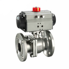
Wiring diagram of pneumatic welding ball valve for heat supply The surface morphology of the laser plasma sprayed coating is obviously different from that of the untreated substrate, indicating that the dominant wear mechanism is different. The surface layer of the wear scar presents obvious furrow characteristics, that is, the micro cutting process is obvious. At the same time, under the load, the abrasive grains press into the friction surface to produce marks, which extrudes the plastic material surface into layered or scaly peeling chips. Therefore, the coatings prepared by plasma spraying process are mainly abrasive wear. The appearance of flaky peeling and plastic deformation characteristics indicates that adhesive wear exists in the matrix, indicating that abrasive wear is no longer the main wear mode, which may be the combination of adhesive wear and fatigue wear when the matrix is paired with the original friction pair, and fatigue wear is the main wear mode.
2.3 Coating bonding strength and thermal shock performance The bonding strength and thermal shock performance of the coating and the substrate have an important impact on the operation of pneumatic ball valves under high temperature conditions. The bonding strength between Al2O3-TiO2 cermet coating and substrate is the highest, reaching 60.40MPa, while the bonding strength of WC Co cermet coating is only 39.45MPa. The internal porosity of the coating and whether the linear expansion coefficient of the coating and the substrate match are the main reasons affecting the adhesion of the coating. According to the test results, Al2O3-TiO2 cermet coating has the best bonding performance with the valve core ball. After 100 times of cold and hot cycles, the Al2O3-TiO2 cermet coating did not produce any obvious cracks and peeling, while the WC Co cermet coating appeared obvious cracks after 6 times and began to fall off after 8 times. Al2O3-TiO2 cermet coating has better thermal shock resistance than WC Co cermet coating due to its better linear expansion coefficient than WC Co cermet coating and substrate. 3 Conclusion 1) Both cermet coatings have high microhardness and small porosity, compact structure, no obvious cracks, and typical layered structure.
2) The wear resistance of the friction pair composed of cermet coating is significantly improved compared with the original friction pair. The wear mechanism of the coating friction pair is mainly abrasive wear; The original friction pair pairing is mainly fatigue wear.
3) The experimental research on the wear resistance, microhardness, bonding strength and thermal shock resistance of the laser plasma spraying coating shows that the comprehensive performance of Al2O3-TiO2 cermet coating is better than that of WC Co cermet coating. Al2O3-TiO2 cermet coating can be used as the spraying coating for remanufacturing high-temperature pneumatic ball valve.
Application of spherical compensator in steam pipe
The metal compensator is very important to fix the reactor
1. The model, specification and pipeline configuration of the compensator shall be checked before installation, which must meet the design requirements.
2. For the compensator with inner sleeve, attention shall be paid to make the direction of the inner sleeve different from that of the medium, and the hinge rotation plane of the hinge type compensator shall be different from that of the displacement rotation plane.
3. For the compensator that needs to stop "cold tightening", the auxiliary components used for pre deformation shall be removed before the end of the pipeline device.
4. It is forbidden to adjust the device out of tolerance of the pipeline by means of deformation of the corrugated compensator, so as not to affect the normal function of the compensator, reduce the service life and increase the load of the pipeline system, equipment and supporting members.
5. In the process of installation, welding slag is not allowed to splash on the surface of the corrugated shell, and the corrugated shell is not allowed to suffer from other mechanical damage.
6. After the completion of the pipe system device, the yellow auxiliary positioning components and fasteners used for device transportation on the corrugated compensator shall be removed as soon as possible, and the limit installation shall be adjusted to the regular position according to the design requirements, so that the pipe system has sufficient compensation ability under environmental conditions.
With the development of urban central heating, the establishment scope of steam pipe network thermal system is becoming larger and larger. In the establishment of steam pipe network, there is an urgent need for a safe, reliable and economical installation of thermal pipe compensation. The spherical compensator plays its good compensation effect, and has been widely used in heat supply pipelines. Now, let's briefly analyze the application of spherical compensator in steam pipeline.
1、 Role of spherical compensator
The working principle of the spherical compensator is relatively simple. In addition to being able to rotate arbitrary angles along the axis, it can also make a certain amount of angular flexion. The spherical compensator uses this angular flexion, and two or three of them are matched into a group to absorb the thermal shrinkage of the pipeline, so as to achieve the purpose of thermal compensation. Spherical compensation has the following characteristics:
1. The compensation ability is large, the deformation stress is small, the partial resistance is small, and the occupation space is small. In the pipeline design, the spacing of fixed supports can reach 300-600 m.
2. It can reduce heat loss and pressure loss, save energy and investment.
3. The length of the pipeline, the number of elbows and compensations are greatly reduced, thereby reducing the temperature drop and pressure drop of the steam, and meeting the user's requirements for steam parameters.
2、 Precautions for spherical compensator device
In practical operation, the spherical compensator shall prevent leakage and put off the support during the installation process. On the long interval straight pipe section on both sides, guide supports shall be set at certain intervals. The movable support shall be a rolling support or a polytetrafluoroethylene plate shall be padded under the sliding support to reduce the pipe friction. In addition, during pipeline laying, sufficient space must be reserved in the center of the spherical compensator to avoid mutual influence of the spherical compensator, so as to ensure the normal free movement of the compensator.