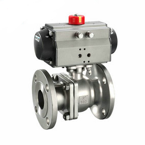
Standard for grounding lug of small flow pneumatic dust ball valve The structural principle is: when the ball is assembled without preload, it is tangent to point A. The preload makes the ball axis displacement, which is generally between 0.2 and 0.4 (mm). When the ball is under pressure, the ball clings to the sealing surface in the direction of pressure. At this time, the seal ring expands outward, so that the sealing surface and the spherical surface will not stick too tightly, causing torque increase. After pressure relief, The sealing valve seat basically returns to the original installation position. Self sealing is a special sealing form. The valve rod seal of the large caliber pneumatic ball valve produced by the valve adopts this structure. The working principle is to use the medium pressure for self tightening sealing. Its sealing ring is installed outside the inner cone and forms a certain angle with the opposite side of the medium. The medium pressure is transmitted to the inner cone to transmit to the sealing ring. Two components are generated on the conical surface at a certain angle. One is parallel to the centerline of the valve body and the other is pressed to the inner wall of the valve body. The latter force is the self tightening force, The greater the medium pressure, the greater the self tightening force. Considering the sealing at low pressure, a certain pre tightening force must be added on the self tightening seal to ensure its sealing performance.
The elbow force balanced bellows compensator is used for the connection between equipment and equipment. Its function is to compensate the heat shrinkage of the pipeline between two equipment, reduce the force of device error on the equipment and facilitate the device. The bending force balanced corrugated contraction is adopted to save energy, so that the equipment is not subject to the blind plate force generated by internal pressure. The rotary compensator improves the stress of the equipment, and the equipment is fixed at random.
The corrugated contraction joint has excellent flexibility and excellent performance when it is used to absorb the displacement generated by pipe heat contraction and the vibration generated by the machine. However, due to its excellent flexibility, if the device is improper, it will not only fail to play its excellent performance, but also easily be destroyed. Therefore, it is very important to correctly stop the support design and force calculation for the pipeline with contraction joints, calculate the transverse and longitudinal displacement and its force state, and accurately select the spacing between various supports and supports.
(1) The bellows contraction joint shall be selected according to the demand of the pipe system and the rated compensation amount. The pretension and compression test of the bellows contraction joint shall be stopped before leaving the factory. The pretension and compression test must meet the design requirements.
(2) The bellows contraction joint selected shall meet the application requirements, and its specification and model shall meet the design requirements and be different from the pipe system design. Contraction joints that do not meet the design requirements shall not be used.
(3) The corrugated pipe contraction joint with diversion pipe shall insist on diverging from the flow direction of the medium, so as to prevent the collection of sundries from affecting the use of the corrugated pipe contraction joint.
(4) It is forbidden to use the deformation of the bellows contraction joint to forcibly adjust the device error with the pipeline when installing the bellows contraction joint, so as not to affect the normal operation function of the bellows contraction joint. The rotary compensator will certainly reduce the service life of the bellows contraction joint.
(5) The bellows shrink joint device shall be installed in cold state, and the device error shall be controlled at: the center line of the interface between the two ends of the pipe and the bellows shrink joint shall be kept on the same center line, the coaxiality error shall be ± 5mm, and it shall not exceed ± 15mm under working state; The deviation displacement angle from top to bottom or from left to right is ± 0.1 °; The reasonable device length of contraction joint is L ± 5mm.
(6) After the installation of bellows contraction joint, remove the auxiliary positioning components and fasteners used as devices and transportation on the bellows contraction joint as soon as possible, and adjust the limit installation to the regular position according to the design requirements, which is the ability for the pipeline to have sufficient compensation under environmental conditions.
(7) For bellows contraction joints and pipes used for gas medium, temporary supports shall be added before filling water to support the weight of liquid medium when hydraulic test is conducted with liquid (water).
(8) During the initial commissioning, maintenance measures shall be taken for the bellows contraction joint at the parts with large air flow impact. After the pipe system operates normally, maintenance and installation shall be removed. The direction of the medium shall be different from the arrow direction of the bellows contraction joint.