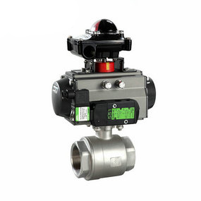
What to do if the pneumatic gas butterfly valve does not return? 3. Refer to DNV-OS-C401 (Det Norske Veritas) standard for safety assessment, and it is qualified if the CTOD value is greater than 0.15mm. Actual measurement of development process joint; C is greater than 0.15mm, indicating that the joint can be used without heat aging treatment. Fig. 3 The relationship between the allowable defect size and the maximum allowable strain of different CTOD values is shown in Appendix A of API 1104 Welding of Pipes and Related Facilities, which gives the relationship between the allowable defect size and the allowable strain when the TCTOD values are 0.005 in (0.1225 mm) and 0.01 in (0.245 mm) respectively, as shown in Fig. 3. It can be seen from the figure that the larger the CTOD value is, the better the fracture toughness of the weld is, and the allowable defect size can be increased. According to the curve between the maximum allowable axial strain and the allowable defect size when the minimum CTOD value of the welded joint of the all welded valve body is equal to 0.197mm (0.0078in).
1、 The use method and working principle of the dual purpose fixture for machining the outer and inner spherical surfaces The use method and working principle: firmly clamp the main body on the square tool rest of the lathe, so that the upper tool tip of the lower bar is in the same plane with the axis of the lathe spindle. The tailstock taper handle 7 is inserted into the tailstock taper hole of the machine tool. The center distance between the two pin holes of the connecting rod 5 is equal to the spherical radius of various sizes to be machined. When machining the inner spherical surface of the valve body, use the pin 6 to connect the connecting rod 5 of the required size to the lower rod 4. After the tailstock is adjusted and fixed, the inner spherical surface can be turned out by the horizontal automatic tool feeding of the middle carriage (or the manual tool feeding of the middle carriage). When machining the outer spherical surface of the valve core, connect the connecting rod 5 with the tailstock taper handle 7 of the upper rod 2. Adjust and fix the distance of tailstock. When the middle carriage is in cross feed, the upper rod 3, under the action of the connecting rod 5, moves longitudinally with respect to the main body 1 (when the middle carriage moves from the outside to the inside, the upper rod 2 moves forward with respect to the main body 1; on the contrary, it moves backward) and drives the pinion 3. The pinion drives the lower rod 4 to move in the opposite direction with the upper rod 2. After combining with the cross feed motion of the middle carriage, the outer spherical surface is turned out. The longitudinal feed and cutting depth of the inner and outer spherical surfaces are controlled by the hand wheel feed of the tailstock.