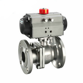
Norm of analog pneumatic slurry butterfly valve sleeve The opening and closing part of the pneumatic ball valve is a sphere with a circular channel, which rotates around the axis perpendicular to the channel, and the sphere rotates with the valve stem to achieve the purpose of opening and closing the channel. The pneumatic ball valve can be closed tightly with only 90 degree rotation and very small rotating torque. According to the needs of working conditions, different driving devices can be assembled to form a variety of pneumatic ball valves with different control methods, such as electro pneumatic ball valve, pneumatic pneumatic ball valve, hydraulic pneumatic ball valve, etc. Working principle of pneumatic ball valve: the working principle of pneumatic ball valve is to rotate the valve core to make the valve unblocked or blocked. The pneumatic ball valve is light to open and close, small in size, can be made into a large caliber, reliable in sealing, simple in structure, convenient in maintenance, and the sealing surface and spherical surface are often closed, not easy to be eroded by media, so it is widely used in various industries. The working principle of the pneumatic ball valve is as follows: when the pneumatic ball valve rotates 90 degrees, it should be spherical at the inlet and outlet, so as to close the valve and cut off the flow of media. When the pneumatic ball valve rotates 90 degrees, the inlet and outlet should be all ball ports, so as to open the flow, and there is basically no flow resistance. The opening process of pneumatic ball valve 1 is in the closed position, and the ball is pressed on the valve seat by the mechanical pressure of the valve stem. 2. When the hand wheel is turned counterclockwise, the valve rod moves in the opposite direction, and the angular plane at the bottom makes the ball detach from the valve seat. 3 The valve rod continues to lift and interacts with the guide pin in the spiral groove of the valve rod to make the ball begin to rotate without friction. 4 Until it reaches the fully open position, the valve rod is lifted to the limit position, and the ball rotates to the fully open position. When the pneumatic ball valve is closed during the closing process 1, rotate the hand wheel clockwise, the valve rod starts to drop and the ball starts to rotate away from the valve seat. 2 Continue to rotate the handwheel, and the valve rod is acted by the guide pin embedded in the spiral groove on it, so that the valve rod and the ball can rotate 90 at the same time. 3 When the valve was about to close, the ball had rotated 90 ° without contacting the valve seat. 4. For the last few turns of the hand wheel, the structural principle of the angular plane mechanical pneumatic ball valve at the bottom of the valve stem: 1. The pneumatic ball valve is not limited by the installation direction, and the flow direction of the medium can be arbitrary. The fluid resistance is small, and the full bore pneumatic ball valve basically has no flow resistance. 2. The pneumatic ball valve is simple in structure, relatively small in size, light in weight and easy to maintain. 3. Tight and reliable. It has two sealing surfaces. At present, various plastics are widely used as the sealing surface materials of pneumatic ball valves, which have good sealing performance and can achieve complete sealing. It has also been widely used in vacuum systems. 4. Pneumatic ball valve is suitable for frequent operation, with quick and convenient opening and closing. It is easy to operate and can be opened and closed quickly. It only needs to rotate 90 ° from full opening to full closing, which is convenient for remote control. 5. Easy maintenance, simple structure of pneumatic ball valve, generally movable sealing ring, easy removal and replacement. 6. The pneumatic ball valve has good sealing performance. When the valve is fully opened or closed, the sealing surfaces of the ball and valve seat are isolated from the medium. When the medium passes through, it will not cause erosion of the valve sealing surface. 7. It has a wide range of applications, ranging from a few millimeters to several meters in diameter, from high vacuum to high pressure. 8. Pneumatic ball valve can be used in media with suspended solid particles due to its wiping property during opening and closing. 9. The pneumatic ball valve has small fluid resistance, no vibration and low noise. Category of pneumatic ball valves: pneumatic ball valves include: floating ball pneumatic ball valve, fixed ball pneumatic ball valve, rail pneumatic ball valve, V-shaped pneumatic ball valve, three air pneumatic ball valve, stainless steel pneumatic ball valve, cast steel pneumatic ball valve, forged steel pneumatic ball valve, ash unloading pneumatic ball valve, sulfur resistant pneumatic ball valve, pneumatic pneumatic ball valve, electric pneumatic ball valve, ferrule pneumatic ball valve, welding pneumatic ball valve. Pneumatic ball valve transmission classification 1. Pneumatic pneumatic ball valve 2. Electric pneumatic ball valve 3. Hydraulic pneumatic ball valve 4. Pneumatic pneumatic ball valve 5. Electro hydraulic pneumatic ball valve 6. Turbine driven pneumatic ball valve Pneumatic ball valve model preparation method: With the acceleration of the development of industrial machinery manufacturing industry, the application of valve products has also developed from low pressure and normal temperature to high pressure and high temperature with the social and industrial progress, The use of pneumatic ball valves is also increasing year by year. The models of pneumatic ball valves used in different media requirements and different working conditions are also different. The editing method of pneumatic ball valve models provided by Watto Valve here is mainly from the increase of additional conditions of pneumatic ball valves, the selection of driving methods, different connection forms, changes in structural forms, types of sealing materials It is convenient to explain the pressure of the valve and the valve body material, which is convenient for users to select the type of Watto pneumatic ball valve and correct understanding of the purchase of pneumatic ball valve. Indication method of pneumatic ball valve model preparation: pneumatic ball valve additional code: V indicates that the valve core has V-shaped structure, D indicates low temperature, B indicates insulation, P indicates eccentric structure, U, S and DY indicate top mounted type; Name code of pneumatic ball valve: Q refers to pneumatic ball valve; Pneumatic ball valve drive code: 2 indicates electro-hydraulic, 3 indicates turbine, 6 indicates pneumatic, 7 indicates hydraulic, 9 indicates electric and manual without code; Connection code: 1 indicates internal thread, 4 indicates flange type, 6 indicates welding, 7 indicates wafer type; Structure type code: floating type: 1 represents straight flow passage, 2 represents Y-shaped tee, 4 represents L-shaped tee, 5 represents T-shaped tee; Fixed type: 0 means hemispherical straight through, 6 means four-way flow channel, 7 means straight through flow to, 8 means L-shaped tee, 9 means Y-shaped tee; Seal material code: B babbitt, F fluororubber, F46 fluorine lining, H stainless steel, J rubber lining, M Monel alloy, N nylon plastic, Monel P, Y hard alloy, W valve body directly processed; Pressure rating code: 16 means the pressure is 16kg (1.6Mpa), and the maximum pressure can reach 64Mpa; 150LB refers to American standard pound pressure, and the maximum withstand voltage level can reach 2500LB (150LB=1.6MPA/300LB=2.5-4.0mpa/400LB=6.4mpa/600LB=10mpa); 5K represents the daily pressure, and the maximum pressure is 63K; Valve body material code: A titanium and titanium alloy, C carbon steel, I chromium molybdenum steel, P18-8 stainless steel, RMo2Ti stainless steel, S plastic. Example for editing model of pneumatic ball valve: Q641F46-16C pneumatic fluorine lined pneumatic ball valve ①, Q: pneumatic ball valve; ② 6: Indicates that the transmission mode is pneumatic; ③ 4: The connection mode is flange connection; ④ 1: The structure is a floating straight passage; ⑤ F46: The sealing auxiliary material is fluororubber; ⑥ 16: It indicates that the nominal pressure is 1.6MPa; ⑦ C: It indicates that the valve body material is carbon steel.
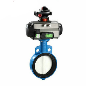
The threading pneumatic butterfly valve and the corrugated pneumatic butterfly valve belong to the same type of pneumatic butterfly valve, and their data requirements, workmanship and application scope are different. Here is a detailed introduction:
Threading pneumatic butterfly valve
The threading pneumatic butterfly valve (English name: Metal Conduit) is made of 304 stainless steel or 301 stainless steel, and is used as the wire and cable maintenance tube for wires, cables, and automatic instrument signals, with specifications ranging from 3mm to 150mm. The ultra small diameter pneumatic butterfly valve (inner diameter: 3mm~25mm) supplied by Tongfeng Pneumatic Butterfly Valve is mainly used for the maintenance of the sensing line of the precision optical ruler and the industrial sensor line. It has excellent delicacy, corrosion resistance, high temperature resistance, wear resistance and tensile resistance. Corrugated pneumatic butterfly valve
Corrugated pneumatic butterfly valve is the main connecting component in engineering technology, which is connected by corrugated flexible pipe, mesh sleeve and joint. It is used as compensation element, sealing element, connection element and damping element in various gas transmission and infusion pipeline systems, as well as length, temperature, location and angle compensation systems, and is used in aerospace, petrochemical, mining electronics, machinery and shipbuilding, medical and health, textile electronics, power construction and other fields.
The latest national standard for corrugated pneumatic butterfly valves is General Technical Premises for Corrugated Pneumatic Butterfly Valves (GB/T14525-2010), which was implemented on October 1, 2011.
The corrugated pneumatic butterfly valve is made of austenitic stainless steel or materials required by the user. It has excellent tenderness, corrosion resistance, high temperature resistance (- 235 ℃~+450 ℃), high pressure resistance (up to 32MPa). It can stop the connection of any tendency in the pipeline to compensate for temperature and accept vibration, reduce noise, change the medium delivery tendency To eliminate mechanical displacement between pipes or between pipes and equipment, double flange metal corrugated hose is especially suitable for flexible joints of various pumps, valves, etc. with displacement and vibration.