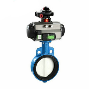
Parameter password of intelligent split pneumatic soft seal butterfly valve There is tensile stress in the chromium plated coating, which has a very adverse effect on the fatigue resistance of the substrate. However, for spraying coatings, the deposited coating can be ensured to be in a compressive stress state by precisely controlling the deposition process. The test results show that the spraying coating has little effect on the fatigue resistance of the substrate. The room temperature high cycle (HCF) and low cycle (LCF) fatigue tests (Figure 6) on chromium plated samples and sprayed coatings show that the fatigue strength of the sprayed coating test is slightly reduced, while the chromium plated samples are significantly reduced, indicating that the impact of the application of sprayed coatings on the fatigue life will be smaller than that of chromium plated coatings.

Design request for pneumatic butterfly valve
Model building request
(1) In order to reduce the model, prevent too many model features, improve the operating speed of the computer, and try to reduce some unnecessary features (such as rounding, chamfering, etc.) when establishing the three-dimensional model of stainless steel pneumatic butterfly valve joint.
(2) It is required to establish the coordinate system of the inlet and outlet ends at the joints. Because it is required to use it in the pipeline design and wiring, there is also a reference point introduced to ensure that the connected pipe joints are straight. If this coordinate system is not established, it will bring inconvenience to the design of the pipeline.
When establishing the coordinate system at the inlet and outlet ends, the guidelines shall be followed:
The direction of the z-axis determines the direction of the wiring. At the outlet end of the pipe joint, the z-axis direction always points to the outer edge of the pipe joint, and the pipeline entry or exit is parallel to the z-axis of the pipe joint.
The coordinate system at the entrance end shall be subject to the practical device junction surface and on the centerline, so that when the designer assembles (the designer shall try to use the coordinate system device when assembling, and can use the ordinary device when it needs to turn a certain angle.) (3) Hide some unnecessary reference features (such as datum plane, axis and coordinate system).
(4) Set up a reference point, place it on the axis, and request that the spacing between the point and the outlet end face be taken as one time of the outer diameter of the pipe joint.


