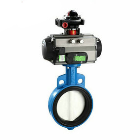
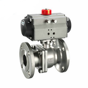
Split pneumatic rubber lined butterfly valve fluctuation state The test was conducted under atmospheric conditions and dry friction conditions. The test temperature was room temperature, the load was 20N, the sliding speed was 4.6m/s, and the total sliding stroke was 1920m. Before and after the test, put the sample into a beaker containing acetone solution, clean it in an ultrasonic cleaner for 3~5min, and then use a Sartorius BS224S electronic balance with an accuracy of 0.1mg to weigh the mass loss of the sensing pin sample before and after wear; Use AF-LI contact and non-contact surface profiler with accuracy of 2 to measure the width and depth of the pit on the worn surface of the disc sample, and calculate the wear volume loss of the pin and disc. The average friction coefficient at the stable stage is selected as the test result, and the arithmetic mean value of the three test results is taken for all wear quantities. According to ASTM-C633-2001 Standard for Bonding Strength Test of Thermal Sprayed Coatings, WE-50 hydraulic tensile tester is used to measure the bonding strength between the coating and the substrate. The thermal shock test of coating is to put the sample into a box type electric furnace at 800 ℃, keep it for 20 minutes, then take it out, put it into cold water at room temperature and quickly cool it to room temperature. Repeat the cycle for 100 times or until the coating falls off. Observe the change of the coating after each thermal cycle, and record the number of thermal cycles for the first crack and the first falling off.

Three Precautions in the Application of Pneumatic Butterfly Valves
There are many precautions in the application of pneumatic butterfly valves, among which there are certain requirements on the sealing connection of non-metallic flat gaskets, the hard sealing connection of metal ball cone, and the laying of buried pipes. Here is a detailed introduction:
1. Sealing connection of non-metallic flat gasket
1) Cut and peel the protective sleeve (covered pipe) away from one end of the buried pipe and use special tools to cut the covered pipe about 50 mm long along the circumference, so that one end of the corrugated pipe is exposed;
2) If the edge of one end of the corrugated pipe has obvious flash, burr or ellipse, use a pipe cutter to cut 1-3 wave rings along the bottom of the corrugated pipe at the exposed end until the inner hole at one end of the corrugated pipe is rounded. If the exposed end length is insufficient after cutting the corrugated pipe, continue to cut and peel the covered pipe to supplement the exposed end length (not less than 50mm).
3) Process the flange and install the connecting nut into the exposed end of the bellows, and then process the flange with the special tool for flange processing. The flange is made by flattening the three waves of the bellows.
4) The seal is connected to the flange flat gasket with the seal ring, and then connected to the joint or valve with the joint nut.
2. Metal ball cone hard sealing connection
1) Cut and peel the protective sleeve (the same connection with the metal flat gasket seal).
2) Cut the bellows (the same connection as the metal flat gasket seal).
3) Install the connecting nut into the exposed end of the bellows, and then use the special tool for bellows expansion to stop the expansion, so that the first wave bottom at one end of the bellows is about the same as the outer diameter of the front and rear wave peaks.
4) For trimming, use a hand-held grinding wheel or scissors to remove the part of the round corner of the orifice at one end of the bellows after bulging, and the edge of the orifice shall be free of burrs after trimming.
5) The conical flange shall be processed with the special tool for processing the conical flange. The corrugated end shall be processed into the conical flange, and the flange surface shall be polished with 200 # sandpaper.
6) The sealing connection is connected with various metal ball cone hard sealing joints or valves by connecting nuts.
3. Laying of buried pipes
1) Grooving on the wall or in the air concrete can be used to embed pipe devices. Grooving on the wall or in the air should be carried out along the direction of pipe laying to meet the needs of laying concealed pipes. The width of the groove shall ensure that the thickness of the pipe cover layer is not less than 20mm on the wall and 100mm in the concrete air.
2) Before laying pipes on the wall and laying buried pipes, use cement nails to fix the pipes in a positive direction (the bayonet faces outward), with the pipe clamp distance of about 200mm, and then push the buried pipes into the pipe clamp for fixation.
3) At the end of the pipeline laying to fill the cover layer, stop the ventilation inspection, use the pressure gauge to pressurize the inspection or use soapy water to coat the joint to check whether the leakage is caused by improper devices. After inspection, if there is no leakage, the materials such as cement can be used to fill the groove and seal the pipeline. The assembly and connection part of the pipeline must be exposed to the wall or the air for easy connection with the appliance.
4) If the buried installation device is not adopted, the exposed pipe device can also be used, and the pipe clamp is also used for isometric connection.


