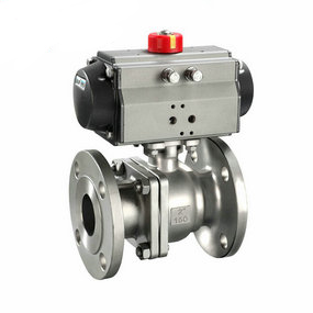
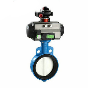
Symbol for pneumatic cut-off butterfly valve of large pipeline Imaginary tool tip and tool tip fillet (A. Imaginary tool tip B. Actual tool cutting point) In order to eliminate the machining error caused by turning tool tip fillet, it is necessary to know the size of tool tip fillet radius first. The result of measuring the tool tip with a tool measuring instrument is R0.21mm. The CNC system of the lathe used for machining is Fanuc OI Mate, which has the function of tool tip arc radius compensation. Therefore, the tool radius compensation command (G41, C42) can be used for tool tip fillet radius compensation. According to the forward direction of the tool path, the tool is located on the right side of the workpiece, so G42 tool compensation command should be used. The tool compensation is related to the orientation of the imaginary tool tip relative to the center of the tool tip fillet (8 orientations in total). The orientation code in Figure 4 is 3. After determining the relevant parameters, first determine the position of the turning tool on the X axis and Z axis with the trial cutting method, and enter the compensation value, then enter the tool tip radius R and the imaginary tool tip orientation code T (see Table 1). Table 1 Tool compensation table Tool complement number XZRT01120900.213 NC machining procedure is as follows: rough machining engineering sequence N50 G00 X0 Z37N60 G42 G01 Z35N70 G03 X0 Z0 R37 F0.05N80 G40 G00 Z37... As long as the tool is set according to the fixed position, machining can be carried out. After cutting, remove the cutter head through the hole with diameter of 28, move the cutter bar along the Z axis (not moving in the X direction), remove the workpiece, install new parts, then set the cutter bar in position, install the cutter head, and continue processing. The test results show that the dimensional accuracy and surface quality of the shell parts of the pneumatic ball valve machined by this method are completely qualified.
Characteristics of high temperature compensator Teflon compensator and preparations before installation
The utility model is characterized in that the corrugated pipe is also provided with two inner liners with displacement joints, and the two inner liners are respectively fixed on the left and right flanges through the outer edges; The first sealing cylinder seals one end of the displacement joint of the inner lining cylinder and is fixed with one side of the lining cylinder; There is a set of L-shaped plates on the second sealing cylinder, the second sealing cylinder is fixed with one side of the lining cylinder through the L-shaped plate, and there is a thermal insulation sealing layer between the second sealing cylinder and the first sealing cylinder; A welding claw is fixed on the side wall of the inner cavity of the compensator, and the heat insulation layer with displacement seam is fixed on the side wall of the inner cavity of the high-temperature compensator through the welding claw. It can not only absorb the three-dimensional displacement caused by the thermal contraction of the CDQ blocking circulating equipment, prevent the generation of internal stress, but also greatly improve the service life of the CDQ circulating hot air equipment.
The high-temperature compensator can not only withstand high temperature, but also has a variety of large displacement compensation quantities, and has a long service life. It is especially suitable for displacement compensation in the installation of blast furnace air supply in steel plants and other places where high-temperature media are escorted. It is significantly improved than the existing compensator. The high-temperature compensator belongs to the category of metal bellows, which is welded into the main body by flange, receiver and bellows. Its interior is equipped with an inner liner pipe, and the middle gap of the inner liner pipe is equipped with a guide cylinder. The high-temperature compensator belongs to the category of metal bellows, which is welded into the main body by flange, receiver and bellows, and is internally equipped with an inner liner. The gap in the middle of the inner liner is equipped with an expansion ring composed of a guide cylinder, a guide cylinder ring plate, a sleeve, and a sleeve ring plate. The guide cylinder and the sleeve are made of oxygen resistant and heat-resistant steel. The local gap between the two stacked PTFE compensators is 5~20mm, The cavity outside the inner liner pipe and the inner cavity of the expansion ring are filled with high temperature resistant insulation materials, and the inner side of the inner liner pipe is poured with high temperature refractory mud.
In the process of installation, welding slag is not allowed to splash on the surface of the corrugated shell, and other mechanical damage to the corrugated shell is not allowed.
After the completion of the pipe system device, the yellow auxiliary positioning components and fasteners used for device transportation on the corrugated compensator shall be removed as soon as possible, and the limit installation shall be adjusted to the designated position according to the design requirements, so that the pipe system has sufficient compensation ability under the environmental conditions.
Before installation, check the model, specification and pipeline configuration of the high-temperature compensator, which must meet the design requirements.
For the compensator with inner sleeve, attention shall be paid to make the direction of the inner sleeve sleeve diverge from the direction of the medium movement, and the hinge rolling plane of the hinge type compensator shall diverge from the displacement rolling plane.
For the compensator that needs to stop "cold tightening", the auxiliary components used for pre deformation shall be removed before the end of the pipeline device.
It is forbidden to adjust the device out of tolerance of the pipeline by means of deformation of the corrugated compensator, so as not to affect the normal function of the high-temperature compensator, reduce the service life and increase the load of the pipeline system, equipment and supporting members.
All moving elements of the high-temperature compensator shall not be blocked or restricted by external components, and the teflon compensator shall ensure the normal operation of all moving parts.
The insulation data in contact with the bellows of the high-temperature compensator shall be free of chloride ions.
During the hydraulic test, the secondary fixed pipe support at the end of the pipeline with the high-temperature compensator shall be reinforced to prevent the pipeline from moving or rolling. For the high-temperature compensator and its connecting pipeline used for gas medium, pay attention to whether temporary support is required during water filling. The 96 chloride ion content of cleaning solution for water pressure test shall not exceed 25PPM.
After the hydraulic test is completed, the accumulated water in the wave case shall be drained as soon as possible, and the internal and external surfaces of the wave case shall be blown dry quickly.