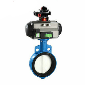
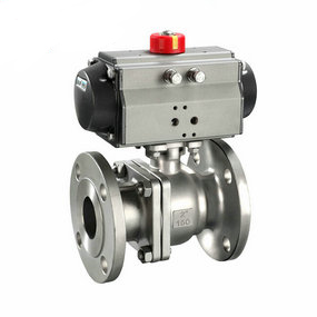
Flow rate range of pneumatic spherical valve for distilled water 3. Refer to DNV-OS-C401 (Det Norske Veritas) standard for safety assessment, and it is qualified if the CTOD value is greater than 0.15mm. Actual measurement of development process joint; C is greater than 0.15mm, indicating that the joint can be used without heat aging treatment. Fig. 3 The relationship between the allowable defect size and the maximum allowable strain for different CTOD values is shown in Appendix A of API 1104 Welding of Pipes and Related Facilities, which gives the relationship between the allowable defect size and the allowable strain when the TCTOD values are 0.005 in (0.1225 mm) and 0.01 in (0.245 mm) respectively, as shown in Fig. 3. It can be seen from the figure that the larger the CTOD value is, the better the fracture toughness of the weld is, and the allowable defect size can be increased. According to the curve between the maximum allowable axial strain and the allowable defect size when the minimum CTOD value of the welded joint of the all welded valve body is equal to 0.197mm (0.0078in).

Analysis of the characteristics of the compensator
The capacitor compensator belongs to the traditional single technology, which can only improve the power factor, reduce the local line loss, and improve the system capacity, but the energy-saving effect is very limited. This kind of equipment has a single function and lacks comprehensive energy saving measures. It has no ability to suppress and filter surges, transients and high-order harmonics, and has poor self adaptability. In applications with large harmonic content, capacitors are easy to be damaged due to overvoltage and overheating. At present, this technology is gradually being eliminated by energy saving equipment of integrated system of system loss reduction.
In the application field, the system compensator can effectively improve the power factor. According to this performance, local customers will mix this product with traditional capacitor compensators. In order to let agents understand the system series power saver more clearly, we make a comparison here. The system compensator integrates contemporary dynamic transient surge suppression and electromagnetic harmonic cancellation technologies, and adopts self-adjusting nano high-capacity devices with large dynamic range, which can effectively reduce the temperature rise of power equipment such as pneumatic actuators formed by transient, reduce internal electromagnetic eddy currents, improve equipment operating efficiency, reduce line losses, improve power factor, and reduce ammeter overmetering, Maintain equipment from transient surge damage, extend equipment service life, and reduce equipment maintenance costs. Therefore, it is an advanced comprehensive system energy conservation and environmental protection maintenance equipment, and its comprehensive benefits are very significant.
The insulation data in contact with the bellows of the compensator shall be free of chloride ions. When the universal compensator is installed, the screw rod cannot be removed, and it can be removed after pressing and normal operation, and the inner nut can also be loosened.
1. During the installation, welding slag is not allowed to splash on the surface of the corrugated shell, and the PTFE compensator is not allowed to suffer other mechanical damage to the corrugated shell.
2. After the completion of the pipe system device, the yellow auxiliary positioning components and fasteners used for device transportation on the corrugated compensator shall be removed as soon as possible, and the limit installation shall be adjusted to the regular position according to the design requirements, so that the pipe system has sufficient compensation ability under environmental conditions.
3. During the hydraulic test, the secondary fixed pipe support at the end of the pipeline equipped with the compensator shall be reinforced to prevent the pipeline from moving or rotating. For the compensator used for gas medium and its connecting pipeline, pay attention to whether temporary support is required during water filling. The 96 chloride ion content of cleaning solution for water pressure test shall not exceed 25PPM.
4. The type, specification and pipeline configuration of the corrugated compensator shall be checked before installation, which must meet the design requirements.
5. For the compensator with inner sleeve, attention shall be paid to make the direction of the inner sleeve different from that of the medium, and the hinge rotation plane of the hinge type compensator shall be different from that of the displacement rotation plane.
6. For the compensator that needs to stop "cold tightening", the auxiliary components used for the pre deformation of the PTFE compensator shall be removed before the end of the pipeline device.
7. All moving elements of the compensator shall not be blocked or restricted by external components, and normal operation of all moving parts shall be ensured.
8. It is forbidden to adjust the device out of tolerance of the pipeline by means of deformation of the corrugated compensator, so as not to affect the normal function of the compensator, reduce the service life and increase the load of the pipeline system, equipment and supporting members.


