Electric gas ball valve manual which price is cheap? How to solve common faults of electric ball valve
Common faults of electric ball valve are as follows:
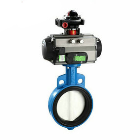
1. The electric ball valve, valve joint and pneumatic valve are mostly connected by flange. The sealing parts, sleeve parts, flanges, fasteners and other supporting pipe fittings required for flange connection must be supplied by the pipe fitting manufacturer; Electric melting connection and hot melting connection shall be constructed with special electrical equipment, extrusion welding equipment and tools;
2. When the electric ball valve is connected, the connection parts, seals, sleeves and other accessories must be cleaned up. Steel sleeves, flanges, clamps, bolts and other metal products used for sleeve (belt or sleeve) connection, flange connection, clamp connection should be taken anti-corrosion measures according to the site soil and relevant standards;
3. The socket flexible interface connection should be carried out when the temperature is high on the day. The socket end should not be inserted into the bottom of the socket. An expansion gap of not less than 10mm should be left. Before insertion, the insertion depth should be marked on the outer wall of the socket end; After insertion, the clearance around the socket shall be uniform, and the connected pipes shall be straight;
4. Electric melting connection, hot melting connection, sleeve electric ball valve (with or with sleeve) connection, flange connection and clamp connection shall be carried out when the temperature of the day is low or near the lowest; The temperature control and time control of electric heating equipment during electric fusion connection and hot fusion connection, and the operation of welding equipment during extrusion welding must be carried out in strict accordance with the technical indicators of joints and the operating procedures of equipment; The joint shall have smooth and symmetrical outer flanging along the circumference of the pipe joint, and the inner flanging shall be flattened. 5. Flexible connection should be adopted between the pipeline and the well chamber, and the connection mode should meet the design requirements; If there is no design requirement, socket pipe connection or intermediate layer method can be used.
6. Technical measures such as concrete buttress or metal clamp pull rod shall be taken at the elbow, tee and reducer of the pipeline system; Concrete buttress shall be padded at the bottom of fire hydrant and gate valve; For non locking socket connection pipes, each pipe joint shall be provided with more than 3 points of fixing measures.
7. After the center line and elevation of the installed pipeline are adjusted to be qualified, the effective support angle range of the pipe bottom shall be backfilled with medium coarse sand and shall not be backfilled with soil or other materials.