Non full pipe pneumatic fluorine lined wafer ball valve ppt 1. Remove the protective covers on both sides of the flange end, and flush and clean the valve when the valve is fully opened.
2. Before installation, the whole machine shall be tested according to the specified signal (electricity or gas) (to prevent vibration caused by transportation from affecting the service performance), and it can be installed online only after it is qualified (wiring shall follow the circuit diagram of electric actuator).
3. Before preparing to connect with the pipe, the residual impurities in the pipe must be flushed and removed (these substances may damage the valve seat and ball).
4. During installation, please do not use the actuator part of the valve as the lifting point to avoid damage to the actuator and accessories.
5. This type of valve shall be installed in the horizontal or vertical direction of the pipeline.
6. The pipeline near the installation point shall not sag or bear external force, and the pipeline support or support can be used to eliminate the deviation of the pipeline.
7. After connecting with the pipeline, please cross lock the flange connecting bolts with the specified torque.
1 Design request for pneumatic butterfly valve
The pneumatic butterfly valve is welded from the local part of the mesh body and the connection joints at both ends. The mesh body is welded from the metal bellows, receiver, ring and steel wire mesh sleeve. Restricted by the structure of the metal bellows, the pneumatic butterfly valve cannot be excessively bent and accept axial load. When it receives torsional stress or alternating stress, its life will be greatly shortened. Therefore, the pneumatic butterfly valve needs to be reasonably installed and fixed in the limited space on the starter, and also needs to meet the motion displacement compensation request, which is difficult.
Figure 1 Pneumatic Butterfly Valve System
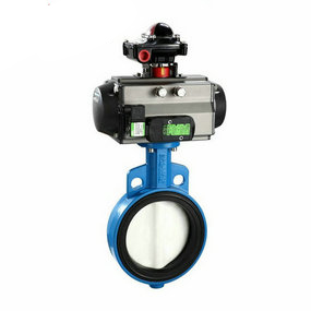
Figure 2 Structure of Pneumatic Butterfly Valve
1.1 System request
(1) Complete the pipeline interface connection between the initiator and the accessory gearbox of the aircraft.
(2) The initiator and the accessory gearbox of the equipped aircraft share the lubricating oil system, and the pneumatic butterfly valve completes escorting the working medium of the lubricating oil system, as shown in Figure 1. 1.2 Structure size request (1) According to the space position and interface request of a certain type of initiator and aircraft accessory gearbox, the pneumatic butterfly valve adopts the combination structure of hard pipe and hose. Through the hard pipe at both ends, the space angle between the initiator and the aircraft accessory gearbox interface is converted into a plane angle, so that the flexible part of the hose becomes a circular arc structure in one plane. The structural dimensions of pneumatic butterfly valve are shown in Figure 2.
Pneumatic butterfly valve
2 Calculation method and steps
2.1 Length calculation
The length calculation of the hose mainly includes two steps: the confirmation of the hose path and the calculation of the path length. Based on the principle of data mechanics, after the average hose is constrained at both ends, the centerline shape should at least meet the second order lubrication continuity; Based on the principle of advanced mathematics, a cubic spline curve can be uniquely affirmed when the coordinates of the starting point and the end point of the curve and the external tangential vector are known.
Take the center coordinates of the end face of the connector provided in Table 2 as the center coordinates of the start and end faces of the hose, take the external vector of the end face of the connector as the internal vector of the end face of the hose, and use the spline curve to stop fitting the hose path. The detailed fitting method is:
(1) Take the starting point as the coordinate origin O, and take the starting point end line as the connection line about a certain working condition to stop the spline curve fitting to get the way. In other displacement compensation working conditions, the shape of the hose will inevitably change, and the radius of curvature will also change. In this paper, the finite element method is used to calculate the deformation under other working conditions (as shown in Figure 5). The following assumptions are used for the hose profiling modeling:
(1) With respect to the hose body, the pipe joint and related components are relatively rigid. It is assumed that in displacement compensation, the end face of the joint only needs to move horizontally without rotation.
(2) The wavelength of the corrugated pipe in the hose is small relative to its length, the wall thickness is thin, and the mesh sleeve is uniform along the length direction. It is assumed that the sectional inertia of the hose body is evenly distributed along its length direction.
The detailed implementation steps are:
(1) Establish the path curve model of the hose under the condition of spline curve; (2) Pipe unit is used to divide the path curve stop unit;
(3) Input pipe section size parameters and data information;
(4) One end stops the complete zero displacement constraint, and the other end applies translational displacement according to the displacement value required by the compensation condition, and constrains the rotational displacement