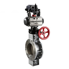
Which one is better for the principle mechanism diagram of stainless steel pneumatic ball valve? Development of pneumatic butterfly valve research in China
The research on pneumatic butterfly valves in China began in 1957, which was limited to pneumatic butterfly valves for vehicles. Then under the leadership of Academician Guo Konghui, a preliminary study on the theory of pneumatic butterfly valves was carried out, several articles on the theory of pneumatic butterfly valves were published, many tests were made, and some experience was accumulated [21]. In the early 1980s, Changchun Automobile Research Institute carried out research on pneumatic butterfly valve suspension, and several domestic automobile factories designed pneumatic butterfly valve suspension. In the 1990s, relevant domestic research institutions, large automobile factories and some universities have started the research and development of pneumatic butterfly valve products. For example, Tongji University and Anhui Jianghuai Automobile Chassis Co., Ltd. will cooperate with a total of five bus chassis ball valves to modify the suspension to pneumatic butterfly valve suspension
It is necessary to design a pneumatic butterfly valve pressure plate to constrain the size simulation of the pneumatic butterfly valve under the air charging state of the pneumatic butterfly valve and to constrain the size of the pneumatic butterfly valve under the air charging state of the pneumatic butterfly valve for simulation loading. The pressure plate of the pneumatic butterfly valve is in the form of a screw with a diameter of 30mm. The large end is used to restrain the pneumatic butterfly valve. Considering the different dimensions of the pneumatic butterfly valve, the diameter of the pressure plate is preliminarily determined to be 300mm. The small end controls the movement of the pressure plate up and down. The positioning of the pressure plate of the pneumatic butterfly valve is completed by the upper and lower guide rails, which not only constrain the displacement of the sliding block in the up and down directions, It can also transmit the pressure of the bogie on the pressure plate of the pneumatic butterfly valve to the crossbeam of the gantry. It opens between two sliders Φ 30 threaded hole, which is matched with the screw. The screw is rotated by two hand wheels, which can realize the up and down movement of the pressure plate of the pneumatic butterfly valve.
The main difficulty of using finite element method to analyze the strength of pneumatic butterfly valve is to determine the mechanical parameters of cord material. The existing equations can not describe its performance very accurately. Moreover, the modulus and strength of cord are closely related to its twisting number and processing technology. Therefore, When using numerical method to analyze the cord strength, it is best to use the test value and combined with the composite equation to determine the parameters used in the calculation. In addition, the analysis carried out in this paper is only the strength of the pneumatic butterfly valve under static load, and when the pneumatic butterfly valve is subjected to dynamic load, Fatigue analysis is required for cord material to determine whether the bonding strength between cord and meets the requirements without peeling.


