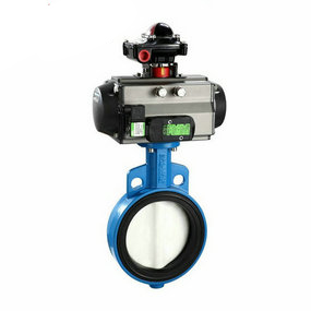
Which one is better for the schematic organization diagram of the wafer type pneumatic butterfly valve? At this time, the friction between the hole wall and the oil and the internal friction between the oil molecules form a damping force on the vibration, so that the vehicle vibration energy is converted into oil heat energy, which is then absorbed by the pneumatic ball valve and distributed to the atmosphere
When the oil channel section and other factors remain unchanged, the damping force increases or decreases with the relative speed of motion between the frame and the axle (or wheel), and is related to the oil viscosity. Pneumatic ball valves and elastic elements bear the task of cushioning impact and valves. Excessive damping force will deteriorate the elasticity of the suspension, or even damage the connecting parts of the pneumatic ball valves
Therefore, the contradiction between elastic element and pneumatic ball valve should be adjusted
During the compression stroke (the axle and the frame are close to each other), the damping force of the pneumatic ball valve is small, so as to give full play to the elastic role of the elastic elements and mitigate the impact
At this time, elastic elements play a major role
During the suspension stretching stroke (the axle and the frame are far away from each other), the damping force of the pneumatic ball valve should be large, and the valve should be quickly opened


